Patented Technology
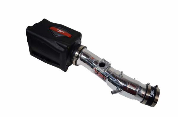
THE RACE TO DEVELOP THE WORLD'S FIRST TUNED AIR INTAKE
The evolution of the entire Injen intake line is paved with industry firsts and innovative designs. Cold air intake design prior to 1996 was a relatively straight forward process, but when OBD II became mandatory for all new vehicles, the game changed forever. Real time monitoring of the vehicle's engine forced aftermarket manufacturers to start engineering their products to perform in harmony with the vehicle's electronics. As the years passed, the OBD II processors became faster and faster, which allowed the ECM (Engine Control Module) to become smarter and adapt to changes and/or modifications quicker.
THE PROBLEM IS IDENTIFIED
In 2003, Injen Technology started designing two separate intake systems; one for the 2003 Mazda 6 and one of the 2002 Subaru WRX. It was business as usual inside Injen's R&D department, but this time, something had changed with the ECM and how quickly it interpreted the information it received from various sensors. No matter what intake tube design the R&D department came up with, the ECM would adjust the air/fuel ratio from one hour to the next to compensate for the changes our intake provided. This might not sound like a big deal to most, but Injen Technology intakes rely on two key characteristics to produce power - improved airflow AND a tuned air/fuel ratio to extract every last ounce of safe power. If the ECU was now tuning around Injen air/fuel adjustments, this obviously posed a severe problem that required revolutionary solutions.
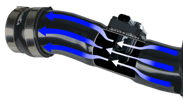
HOW A MASS AIR FLOW SENSOR WORKS
Many of the applications in which Injen designs its cold air intakes are for use on a Hot Wire style Mass Air Flow Sensor. Within this sensor there is a wire placed in the airflow path and a specific amount of current is required to maintain the elevated temperature of the “hot wire”. As mass air flow increases, the wire is cooled. As the wire cools, the resistance within the wire decreases. A decrease in resistance allows additional current flow to maintain the wire’s “hot” temperature. That current required to maintain that hot wire temperature is interpreted by the ECM as a specific mass airflow. The ECM will adjust fuel injection to match the available airflow in order to maintain proper air/fuel ratios.
AN UNDERSTANDING
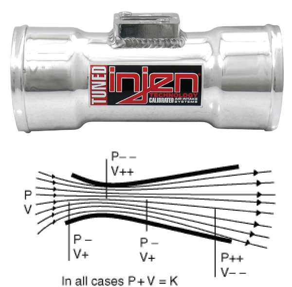
The challenge of controlling the mass air flow sensor for our air/fuel ratio adjustments without the use of add-on electronics reminded our engineers to go back to the basics. Those basics being the principles developed in the 18th century by Bernoulli. In its most basic form, Bernoulli’s Principle reminded our engineers that in order to keep our mass flow consistent (or to increase mass flow), there are dynamic changes that must occur within an intake tube in order to guarantee sufficient air is being supplied to the engine. These dynamic changes are governed by very specific laws of physics and we needed to harness those laws to extract every last bit of power safely and without causing check engine lights. For example, if you have a fluid flowing through a pipe of varying cross-sectional areas, the fluid will speed up in the constricted areas and the pressure the fluid exerts is least where the cross section is the smallest. This phenomenon is also called the Venturi effect. Looking further into the works of this 18th century physicist reminded Injen the importance of developing a streamlined air intake system that would provide the least amount of resistance within the intake.
BERNOULLI'S THEOREM
Example: P=pressure and V=velocity
From this law, it follows that where there is a velocity increase in a fluid flow, there must be a corresponding pressure decrease. Swiss physicist and mathematician Daniel Bernoulli formulated this theorem in 1738.
APPLYING WHAT WE'VE LEARNED
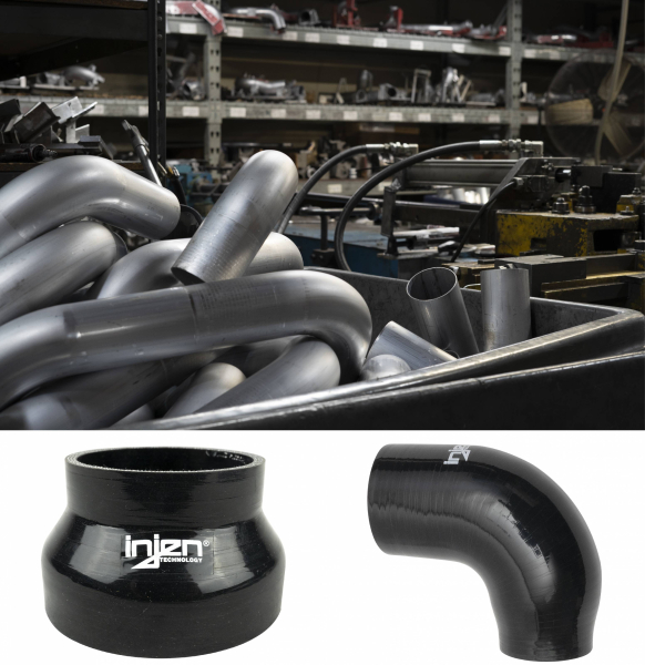
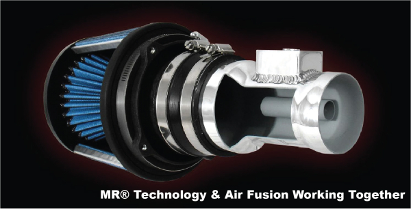
After a few sleepless nights, Injen engineers started considering incorporating a venturi type tube along the path of an intake tract to control the flow rate to the mass air flow sensor. By learning how to control air speed and resultant pressure, Injen engineers were able to maintain the desired temperature of the “hot wire” located inside the mass air flow sensor without the use of external electronics! In doing so, Injen now had the method to tune the air/fuel ratio for optimum power built directly into the Injen intake system.
Along with controlling the air/fuel ratio, Injen also needed a way to control short term and long term fuel trim levels. Short term fuel trim levels refer to adjustments being made in response to temporary conditions. Long Term fuel trim levels compensate for issues the presents itself over a longer time period. Fuel trims are expressed in percentages and can be monitored by accessing the ECM through the OBD II data port. A positive value indicates lean conditions (add fuel) and negative values indicate rich conditions (subtract fuel). Evaluating this data during the R&D process allows our technicians to properly fit and tune Injen’s Air Fusion device if needed.
With all of this research compiled by the end of 2004, Injen began an aggressive restructuring program that would involve a total overhaul of the R&D and production departments. The engineering department began redesigning air filters, couplers, step hoses, and incorporated larger bend tools and forming equipment that would allow us to build a “tuned” intake with the least amount of air resistance for maximum horsepower and torque gains. Today, all Injen filters, molded couplers, and elbows are equipped with built-in velocity stacks. In addition, mandrel bent tubes are bent with larger radiuses for streamlined airflow and intakes are fitted with the correct tube size to minimize the amount of air restriction and maximize engine efficiency.
...AND THE SMOKE SETTLES
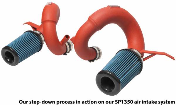
The cat was now out of the bag and every aftermarket enthusiast began experiencing the step-down tuning process known as MR® Technology and referred to as “The World’s First Tuned Air Intake System. This process required no re-calibration of the mass air flow sensor; no re-flashing of the ECU and certainly no electronic devices to trick the on-board computer. The new “Method and Device” was in itself a calibration and tuning process for the intake to be used in conjunction with the stock mass air flow sensor, where all stock parameters remained untouched.
As the new line of SP intakes began to fill the streets, forums got slammed with questions as to how the step-down process actually worked and controlled air/ fuel ratios. As soon as Injen Technology learned that the competition was trying to mimic the method of tuning intakes, Injen immediately began to file for patents to try and stop knock-offs.
25+ YEARS OF INNOVATION
Today, many intake manufacturers are now riding on Injen’s coat tail, using MR® Technology and calling it their own. The Method and Calibration process was invented and perfected by Injen between the years of 2002-2004. Next time you purchase a non-Injen Air intake system and it has the famous MR® Technology, ask the manufacturer how they came up with this MR® step-down process. Remember, Injen Technology is the inventor, the Patent holder and the only one that knows how to truly tune a cold air intake.
